 The
next step is to glue on the soundhole braces. They don't take much clamping
pressure, as the glue soaks right into the spruce. A very thin glue line.
The
next step is to glue on the soundhole braces. They don't take much clamping
pressure, as the glue soaks right into the spruce. A very thin glue line.Home Road Map Resources Lutherie Tools
Another 14-day week, because with house guests for Easter and a visiting relative in New York the next weekend, I just about got one day in the shop over the two weeks.
The
next step is to glue on the soundhole braces. They don't take much clamping
pressure, as the glue soaks right into the spruce. A very thin glue line.
 The
two side soundhole braces are longer due to the geometry of the thing, so they
need a different clamping scheme.
The
two side soundhole braces are longer due to the geometry of the thing, so they
need a different clamping scheme.
 The
finger braces are glued outboard of the X brace in the lower bout. There the
clamping is done on the workboard.
The
finger braces are glued outboard of the X brace in the lower bout. There the
clamping is done on the workboard.
 The
braces are glued "in the square" to give a level surface for the
clamps to bear on, but are then shaped to various rounded profiles. The finger
braces are feathered away to nothing right along the edge of the X brace and a
half-inch or so away from where the sides will be, leaving room for the linings.
Other braces will run right up to the sides, and there will have to be gaps in
the linings to accommodate them.
The
braces are glued "in the square" to give a level surface for the
clamps to bear on, but are then shaped to various rounded profiles. The finger
braces are feathered away to nothing right along the edge of the X brace and a
half-inch or so away from where the sides will be, leaving room for the linings.
Other braces will run right up to the sides, and there will have to be gaps in
the linings to accommodate them.
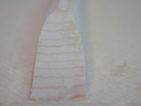
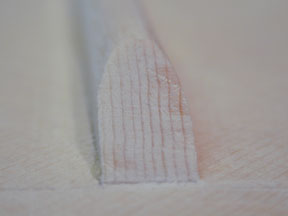
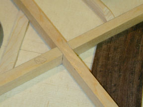
I didn't see anything in Cumpiano and Natelson or on the plans to indicate what the grain orientation should be in the braces. There is a figure in C&N that shows all the braces in cross-section that has hatching that might indicate grain direction, but elsewhere in the book grain direction is plainly marked and labeled with the word "grain" as in the diagram of the headblock. So I didn't pay any attention to the exact orientation of the grain in the braces, taking care only that it should have as little runout as possible, by cutting along the split planes. So some of the braces have annual rings oriented perpendicular to the surface of the soundboard and some are parallel. They must be different in acoustic properties: I would guess the vertical grain in the second picture above would be less flexible. But maybe the difference is negligible.
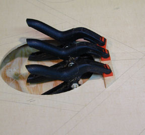
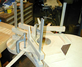 Yes,
it's another photo of my small but elegant collection of clamps. Actually,
there's an important difference between the braces that went before and the one
in this photo and after. These braces are arched slightly along the side that
contacts the soundboard, giving the soundboard a very gentle curvature. The
curve is a deflection of 1/8" at the center of an 18" arc, so it is
barely noticeable. The clamping of these braces must be done using a flexible
caul under the soundboard. In this case it is a strip of 1/8" plywood, that
I had cut to the specified curve and used as a template to mark the braces for
arching. Nothing goes to waste. The caul is needed in order to help ease the
soundboard into the smooth curve against the arched brace.
Yes,
it's another photo of my small but elegant collection of clamps. Actually,
there's an important difference between the braces that went before and the one
in this photo and after. These braces are arched slightly along the side that
contacts the soundboard, giving the soundboard a very gentle curvature. The
curve is a deflection of 1/8" at the center of an 18" arc, so it is
barely noticeable. The clamping of these braces must be done using a flexible
caul under the soundboard. In this case it is a strip of 1/8" plywood, that
I had cut to the specified curve and used as a template to mark the braces for
arching. Nothing goes to waste. The caul is needed in order to help ease the
soundboard into the smooth curve against the arched brace.
 Once
glued, the upper face brace is also rounded and feathered down at the ends. In
this case, however, the end is left 1/8" thick and it goes right to where
the side will meet the top.
Once
glued, the upper face brace is also rounded and feathered down at the ends. In
this case, however, the end is left 1/8" thick and it goes right to where
the side will meet the top.
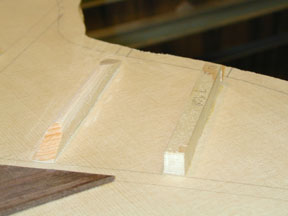
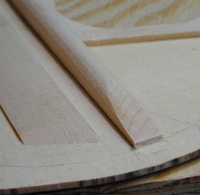
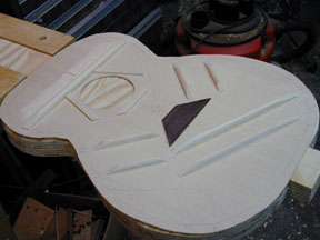 Here
is the layout of all the braces except the X. The lower face braces have been
glued in and shaped like the finger braces. They are also arched like the upper
face brace. As you can see
from this, all the braces except the two uppermost lead into (or away from) the
edges of the X brace. All the ends go right down to the X-brace line, whether
they will feather away or butt up against it.
Here
is the layout of all the braces except the X. The lower face braces have been
glued in and shaped like the finger braces. They are also arched like the upper
face brace. As you can see
from this, all the braces except the two uppermost lead into (or away from) the
edges of the X brace. All the ends go right down to the X-brace line, whether
they will feather away or butt up against it.
 The
X brace is the largest, or rather it consists of the two largest, braces on the
soundboard. The two parts cross symmetrically between the bridge patch and the
soundhole, and the arms of the x contact the bridge patch and the soundhole
braces. There is a lap joint at the point of crossing, that is, each brace is
notched and the two notches interlock. The joint is made with a very exact fit
-- not just as a way to clear the crossing -- to have the most effective
coupling of the two members. In this photo, the braces are just laid into their
position. Like the upper face brace, the X brace is given a slight arch before
being glued into position.
The
X brace is the largest, or rather it consists of the two largest, braces on the
soundboard. The two parts cross symmetrically between the bridge patch and the
soundhole, and the arms of the x contact the bridge patch and the soundhole
braces. There is a lap joint at the point of crossing, that is, each brace is
notched and the two notches interlock. The joint is made with a very exact fit
-- not just as a way to clear the crossing -- to have the most effective
coupling of the two members. In this photo, the braces are just laid into their
position. Like the upper face brace, the X brace is given a slight arch before
being glued into position.
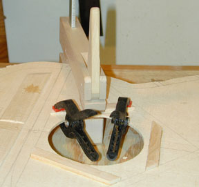
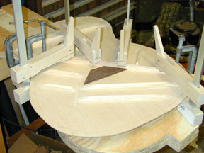 Here
the first X-brace member is being glued. I hope it's the one whose notch faces
up. Actually, I know it is, because I first put the two parts together, then
applied glue to the "lower" member and located the paired braces
against their respective sides of the bridge plate and the soundhole braces. I
then opened the center clamp and removed the unglued brace, concerned that a bit
of glue squeezeout might tack it down and make it difficult to remove
later. When the glue is set under the first member, the clamps are removed, the
flexible caul is moved under the location of the second brace, and the second
brace is glued down and clamped.
Here
the first X-brace member is being glued. I hope it's the one whose notch faces
up. Actually, I know it is, because I first put the two parts together, then
applied glue to the "lower" member and located the paired braces
against their respective sides of the bridge plate and the soundhole braces. I
then opened the center clamp and removed the unglued brace, concerned that a bit
of glue squeezeout might tack it down and make it difficult to remove
later. When the glue is set under the first member, the clamps are removed, the
flexible caul is moved under the location of the second brace, and the second
brace is glued down and clamped.
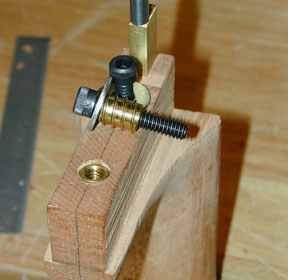 While
the braces were drying I went ahead with installing the neck-bolt hardware.
These brass inserts with their matching bolts are available from LMI, and also
from hardware stores a little cheaper, if you like to poke through those endless racks of drawers
with your little paper bag and golf pencil in hand. I prefer it when it's sort
of in the back and dimly lit and there's an ancient guy hovering around who will
point out that that there is an Allen bolt and how he went to school with Mr.
Allen, and took Shop class with Mr. Philips. Ahem. Sorry. These are from LMI. The brass insert requires a 3/8"
hole, and the hex key for the bolt is 3/16". I point this out for the
enlightenment of innocents like me who find that the information sheet LMI
includes with the bolts and inserts does not include this information. The
insert is not equipped with the usual screwdriver slots, so I threaded two of
the inserts onto one of the bolts, and used the hex key to drive the lower
insert into the hole. It worked pretty well, though it's important to point out
that to install the second insert using my method I had to borrow another insert
from a second pair of these that I ordered along with the boxed materials.
While
the braces were drying I went ahead with installing the neck-bolt hardware.
These brass inserts with their matching bolts are available from LMI, and also
from hardware stores a little cheaper, if you like to poke through those endless racks of drawers
with your little paper bag and golf pencil in hand. I prefer it when it's sort
of in the back and dimly lit and there's an ancient guy hovering around who will
point out that that there is an Allen bolt and how he went to school with Mr.
Allen, and took Shop class with Mr. Philips. Ahem. Sorry. These are from LMI. The brass insert requires a 3/8"
hole, and the hex key for the bolt is 3/16". I point this out for the
enlightenment of innocents like me who find that the information sheet LMI
includes with the bolts and inserts does not include this information. The
insert is not equipped with the usual screwdriver slots, so I threaded two of
the inserts onto one of the bolts, and used the hex key to drive the lower
insert into the hole. It worked pretty well, though it's important to point out
that to install the second insert using my method I had to borrow another insert
from a second pair of these that I ordered along with the boxed materials.
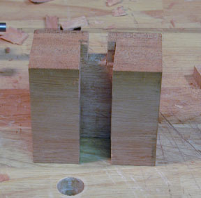 This
is the headblock. The slot running all the way down the front of it will accept
the tenon on the heel of the neck. The small slot all the through it at the top
of the big slot will allow the end of the truss rod to poke through. The
uppermost side in this photo is glued to the underside of the soundboard. The
other end of the block is 1/8" taller on the far side than on the side
facing you in the photo; this accommodates the arch of the guitar back. I'm not
sure how I'll locate the holes for the bolts that will hold the neck on. At this
point on Saturday, I'm too tired to decide if it's worth calculating or I should
use some method to mark it with pointed cut off bolts in the actual inserts.
I'll leave it over until later to decide.
This
is the headblock. The slot running all the way down the front of it will accept
the tenon on the heel of the neck. The small slot all the through it at the top
of the big slot will allow the end of the truss rod to poke through. The
uppermost side in this photo is glued to the underside of the soundboard. The
other end of the block is 1/8" taller on the far side than on the side
facing you in the photo; this accommodates the arch of the guitar back. I'm not
sure how I'll locate the holes for the bolts that will hold the neck on. At this
point on Saturday, I'm too tired to decide if it's worth calculating or I should
use some method to mark it with pointed cut off bolts in the actual inserts.
I'll leave it over until later to decide.
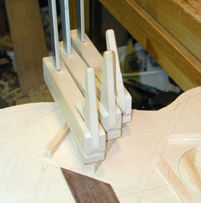
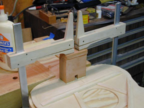 Yes,
the hex nut on the truss rod is only barely accessible over the upper face
brace. I'll need to check this when the glue sets on the headblock. The piece
that was cut off to give a slight angle to the back side of the headblock was
saved and is here used to provide a level clamping surface. Those Messrs C&N
are very clever fellows indeed.
Yes,
the hex nut on the truss rod is only barely accessible over the upper face
brace. I'll need to check this when the glue sets on the headblock. The piece
that was cut off to give a slight angle to the back side of the headblock was
saved and is here used to provide a level clamping surface. Those Messrs C&N
are very clever fellows indeed.
This is the end of the line for these two weeks. I need to cut out and
install a tail block and then I'm ready to bend the sides. So next session is
highly likely to include that adventure.
Home Road Map Resources Lutherie Tools
Copyright © 2001 Stephen Miklos